Saturday, March 4, 2023

The Ins and Outs of Thermocouple Sensors: Understanding Their Function and Applications

Eltronicschool. - Thermocouple sensors are widely used in the field of temperature measurement due to their simplicity, durability, and versatility. A thermocouple is a type of temperature sensor that consists of two different metal wires joined together at one end. When there is a temperature difference between the two ends of the wires, a voltage is generated that is proportional to the temperature difference. This voltage can then be measured and used to determine the temperature.

Thermocouple Sensor (Source: Lazada)

Thermocouples are commonly used in industrial applications, such as in power plants, chemical plants, and manufacturing processes. They are also used in scientific research, automotive engineering, and in the aerospace industry. One of the key benefits of thermocouples is their ability to operate in a wide range of temperatures, from cryogenic temperatures to very high temperatures.

There are many different types of thermocouples available, each with its own unique characteristics and temperature range. Some common types include type K, type J, type T, and type E. Type K thermocouples are the most commonly used and can measure temperatures from -200 to 1,372 degrees Celsius. Type J thermocouples are suitable for temperatures up to 760 degrees Celsius, while type T thermocouples are used for lower temperature ranges up to 370 degrees Celsius. Type E thermocouples are typically used for high-temperature applications up to 870 degrees Celsius.

Thermocouples can be made from a variety of different metals, including copper, iron, and platinum. The specific metal combination used for a thermocouple will depend on the temperature range and accuracy required for the application. Some thermocouples are also coated with ceramic or other materials to improve their durability and resistance to corrosion.

One of the key advantages of thermocouples is their ability to provide real-time temperature readings. They can be used in conjunction with data acquisition systems to provide continuous monitoring of temperature in a variety of applications. This is particularly useful in industrial processes where accurate temperature control is critical to ensuring product quality and safety.

Thermocouples can also be used in a variety of other applications, such as in HVAC systems, refrigeration, and cooking appliances. They are also commonly used in medical devices, such as temperature probes and catheters.

However, there are some limitations to using thermocouples. One of the main limitations is that they can be affected by electromagnetic interference, which can result in inaccuracies in the temperature readings. They can also be sensitive to changes in the environment, such as changes in pressure or humidity.

To overcome these limitations, thermocouples are often calibrated to ensure their accuracy and reliability. Calibration involves comparing the output of the thermocouple to a known reference temperature and adjusting it as necessary to ensure that it is providing accurate readings.

In conclusion, thermocouple sensors are a widely used and versatile type of temperature sensor that can operate in a wide range of temperatures. They are commonly used in industrial applications, scientific research, and in many other fields. While they have some limitations, such as susceptibility to electromagnetic interference, they remain a popular choice due to their simplicity, durability, and reliability.

Monday, April 26, 2021

Circuit Schematic of Charger 12V - 3 to 6Ah Sealed Lead Acid (SLA) Batteries

Eltronicschool. - This is one of the Battery Charger for Sealed Lead Acid batteries that very suitable for dual level float cum boost charger with pre-charge for 12V from 3 to 6 Ah. The main component used in this project is BQ24450 IC from Texas instruments.

In this time we will give you the global descrription and also schematic of this Charger 12V - 3 to 6Ah Sealed Lead Acid (SLA) Batteries and the last we will give you the link to read more about this project from original article.

Circuit Schematic

Figure 1. Circuit Schematic of Charger 12V - 3 to 6Ah Sealed Lead Acid (SLA) Batteries (Source: https://www.electronics-lab.com/)


Component Part


Description

Circuit schematic like in Figure 1 above is CCircuit Schematic of Charger 12V - 3 to 6Ah Sealed Lead Acid (SLA) Batteries. Based on Electronics-Lab blog describe that this SLA Battery charger project is the right choice if you want to obtain maximum battery service life and capacity, along with acceptable recharge time and economy, constant current, constant voltage, and even charge a deeply discharged battery. 

The project contains all the necessary circuitry to optimally control the charging of valve-regulated lead-acid batteries. The circuit controls the charging current as well as the charging voltage to safely and efficiently charge the battery, maximizing battery capacity and life. The circuit is configured as a simple dual-voltage float-cum-boost charge controller. 

It is configured for charging 3 to 6Ah, 12V SLA batteries with dual-level float-cum-boost charger with pre-charge function and provides 500mA current output. The circuit also helps to charge deeply discharged batteries with pre-charge function. In this function Pin 12 (CE) detects the battery voltage, if the voltage at pin12 (CE) is bellow V-ref (2.3V), enable comparator permits a pre-charge current IPRE to flow from the PRE-CHG pin through Resistor R7 into the battery. 

Once the battery voltage rises above a safe threshold, the comparator disables the pre-charge function and IC performs the dual-level charging operations. Connector CN1 provided for supply input, CN2 battery, D3, D2 operation indictor, Jumper J1 connected to GND. Transistor Q1 requires an appropriate heatsink.

For more information about Circuit Schematic of Charger 12V - 3 to 6Ah Sealed Lead Acid (SLA) Batteries, please read more using this [Link]

Monday, December 14, 2020

How to Make High Voltage Half-Bridge With Current Feedback Using L6390

Eltronicschool. - The main component in this project of high voltage half-bridge with current feedback is L6390 IC from ST Semiconductor. With this IC, we can use it to build DC motor speed controller and field-oriented control (FOC) motor driving application, induction heater drivers, DC-DC converters, EHT drivers, battery chargers, and LED drivers.

In this project we will show you the schematic diagram of High Voltage Half-Bridge With Current Feedback Using L6390, all component used, global description, and the last will give you link to read more about this project from original source.

Circuit Schematic

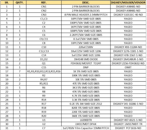
Figure 1. Circuit Schematic of High Voltage Half-Bridge With Current Feedback Using L6390 (Source: Electronics-Lab)


Component Part


Description

Circuit schematic like in Figure 1 above is High Voltage Half-Bridge With Current Feedback Using L6390. From Electronics-lab site describe that the L6390 is a high voltage half-bridge gate driver. This device can be used in all applications where high voltage shifted control is necessary. The devices have a driver current capability best suited for home appliance motor driving ratings, and they are also equipped with patented internal circuitry which replaces the external bootstrap diode. This feature is achieved by means of a high voltage DMOS synchronously driven with the low side gate driver. The L6390 is a half-bridge driver with several functions such as externally adjustable deadtime, interlocking, smart shutdown (patented), fault comparator and a dedicated high-performance op-amp for advanced current sensing. The outputs can be driven by two dedicated logic signals or, alternatively, only one logic signal by connecting the two inputs together. Device outputs can sink and source 430 mA and 290 mA respectively. Prevention from cross conduction is ensured by interlocking and programmable deadtime functions.

Dead Time: R8 provided to set the Dead time. The dead time can be set to a wide range of values from hundreds of nanoseconds to a few microseconds. In order to avoid any possible cross-conduction between the power MOSFETs/IGBTs of the half-bridge, the L6390 provides both the dead time and the interlocking functions. The interlocking function is a logic operation which sets both the outputs to low level when the inputs are simultaneously active (HIN to high level and LIN to low level). The dead time function is a safety time introduced by the device between the falling edge transition of one driver output and the rising edge of the other output. If the rising edge set externally by the user occurs before the end of this dead time, it is ignored and results delayed until the end of the dead time. The dead time can be adjusted externally through the value of the DT resistor R8 connected between pin 5 and GND. A capacitor C4 1 KPF ceramic capacitor in parallel with this resistor is provided for noise immunity.  and interlocking function management are described.

Smart Shut-Down: The L6390 integrates a comparator for fault sensing purposes. The comparator has an internal reference voltage Vref on its inverting input (see L6390 datasheet), while the noninverting input is available on pin 10. The comparator input is connected to an external shunt resistor R17 in order to implement a simple over-current detection function. The output signal of the comparator is fed to an integrated MOSFET with the open drain available on pin 2, shared with the SD input. When the comparator triggers, the device is set in shutdown state and both its outputs are set to low level leading the half bridge in tri-state. In common over-current protection architectures, the comparator output is usually connected to the SD input and an RC network is connected to this SD/OD line in order to provide a mono-stable circuit, which implements a protection time that follows the fault condition. Unlike common fault detection systems, the L6390 smart shutdown architecture allows to immediately turn-off the output gate driver in case of fault, by minimizing the propagation delay between the fault detection event and the actual outputs switch-off. In fact, the time delay between the fault and the outputs turn-off is no more dependent on the RC value of the external network connected to the pin. In the smart shutdown circuitry, the fault signal has a preferential path which directly switches off the outputs after the comparator triggering. At the same time the internal logic turns on the open drain output and holds it on until the SD voltage goes below the SD logic input lower threshold. The smart SD system provides the possibility to increase the time constant of the external RC network (that is the disable time after the fault event) without increasing the delay time of the protection. Any external signal provided to the SD pin is not latched and can be used as control signal in order to perform, for instance, PWM chopping through this pin. In fact, when a PWM signal is applied to the SD input and the logic inputs of the gate driver are stable, the outputs switch from the low level to the state defined by the logic inputs and vice-versa., 

And now you can read more about the project How to Make High Voltage Half-Bridge With Current Feedback Using L6390 from original source using link HERE.

Monday, November 9, 2020

Circuit Schematic of Dimmer Lamp Based on Triac BT136

Eltronicschool. - Do you want to adjust your Halogen lamp, light bulb up to 250 W, we recommend to use this circuit schematic and you can do it yourself. This circuit schematic is Triac Based Lamp Dimmer using BT136 and DB3 as Diac for Triac triggering.

In here beside we will give you circuit schematic of this dimmer lamp, here we also will give you description and feature of this circuit.

Circuit Schematic

Figure 1. Circuit Schematic of Dimmer Lamp Based on Triac BT136 (Source: Electronics-Lab)


Component Part
  1. Triac
  2. Diac
  3. Resistors
  4. Capacitor
  5. Variable Resistor
Description

Circuit schematic like in Figure 1 above is Circuit Schematic of Dimmer Lamp Based on Triac BT136. Triac based Indecent lamp dimmer is a simple circuit and it doesn’t requires additional power supply, works directly with 110V AC or 230V AC.

Based on Electronics-Lab site describe that this circuit is a low cost dimmer circuit for adjusting the light brightness of incandescent, Halogen Lamp, Light Bulb load up to 250 W. this circuit consists of BT 136 Triac, resistors and capacitor.  CN1 connector is for Load connections and CN2 connector for power supply connections.
  • BT136: It is a sensitive gate Triac, used in general purpose bidirectional switching and phase control applications where high sensitivity is required.
  • DB3: It is a DIAC that functions as a trigger diode with a fixed voltage reference.  It can be used in conjunction with Triac for simplified gate control circuits or as a starting element in fluorescent lamp ballasts.

Features:
– Input supply: 230 VAC or 110 VAC
– Output: 250 W
– Triac controlled
– On board Potentiometer for adjusting level
– Power Battery Terminal (PBT) for easy input / output connection
– Four mounting holes of 3.2 mm each
– PCB dimensions 40 mm x 34 mm

How it works

This circuit is used as a Light dimmer kit.  It is used to adjust the brightness of the Halogen Lamp, Light Bulb up to 250 W.  A power supply of 230 or 110 VAC is supplied to the kit at CN 2 connector and a light bulb is connected at the CN 1 connector.  Using the POT we can adjust the brightness of the bulb.

Tuesday, September 29, 2020

AC Dimmer 220V/50Hz for Adjusting Alternating Current Max 2000W

Eltronicschool. - Now we will give you one useful electronic device that called with AC dimmer 220V/50Hz using main component SCR that can be used to adjust the level of alternating current voltage 220V/50Hz.


This product very useful for all of the tools that used 220V/50Hz power motor like Grinder, Electric Drill, motor, and others. This product also very suitable to adjust the temperature of our tools like the soldering iron, oven, and other. You also can use this product to dimme the lamp (not LED) in your home and other.

for more information about this product please visit some link below:

2. OLX