Eltronicschool. - To know how many capacity of water in the tank, we can use indicator level. With indicator level that build in the water tank we can know each level water according the level indicator that we need in the water tank.
Simple electronic circuit schematic to give us information water level indicator can build from few components like transistor, resistor and LED as light indicator in each water level that needed.
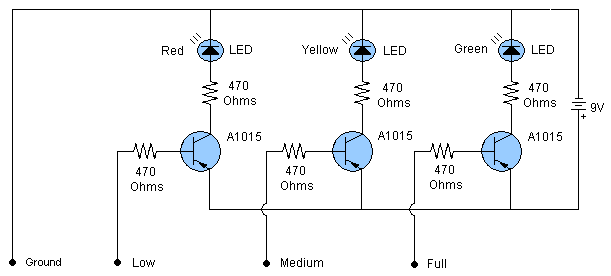
Figure 1 show you simple electronic circuit schematic water level indicator that can help you to give indicator in water tank when you fill it with water.
Circuit Schematic
 |
| Figure 1. Water Level Indicator Circuit (Image: Circuitdiagrams) |
Component List
- Resistor ---> 470 ohm
- Transistor ----> A1015
- Diode ------> LED
Description
Electronic Circuit Schematic Water Level Indicator like in figure 1 above consist of few components and easy to find in electronic market. And here are the description of this circuit schematic:
- he circuit is very easy to build and contains only three PNP transistors and some other components.
- This is a very useful circuit to detect the level of water in the tank.
- The circuit is using three colors LEDs which will indicate low, medium and full level of water in the tank.
- The three probes (Low, Medium, Full) are shown in the circuit to attach on desired levels in the tank.
- The ground probe should be attached at the bottom of the water tank.


0 comments:
Post a Comment
Thank's for your reading in this article, please don't forget to comment.