Eltronicschool. - There are many circuit schematic designed using MOSFET component for many application. One application is Circuit Schematic Low-Cost Dusk-Dawn Controller using MOSFET IRF640 like in Figure 1 below. (You also can read: Circuit Schematic 12V LDO Solar Charge Controller using MOSFET)
Circuit schematic
Component Parts
- LDR
- IRF640 MOSFET
- Resistors
- LED
- All components see in Figure 1 above
Description
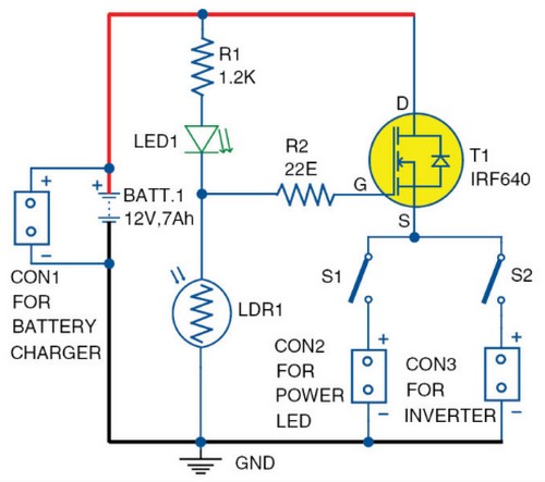
Circuit schematic like in Figure 1 above is Circuit Schematic Low-Cost Dusk-Dawn Controller using MOSFET IRF640. According Electronicsforu site describe that Solar streetlights can be easily integrated with a dusk-dawn controller by simply employing a pnp transistor and a few resistors where the solar panel itself works as the sensor. But what about other lighting sources that do not employ solar panels such as automatic lighting systems in small wind turbines, automatic lighting in cars or battery based systems where automatic lighting is necessary?.
The 12V battery-operated circuit is designed such that the common battery supply is used for operating the circuit as well as for load, that is, for power LED/small inverter circuit. Resistors R1 and R2 are used as a voltage divider and a current limiter in the circuit, respectively. LED1 is used as circuit de-activation indicator. LDR1 is the main component for actuation of the dusk-to-dawn sensing. The n-channel MOSFET IRF640 is for the switching action of the LED light or the small inverter connected to the system through switches S1 and S2, respectively.
Please read more about the Circuit Schematic Low-Cost Dusk-Dawn Controller using MOSFET IRF640 from original source using the link here.


0 comments:
Post a Comment
Thank's for your reading in this article, please don't forget to comment.