Showing posts with label Audio Circuit. Show all posts

Monday, April 3, 2017

Simple Circuit Schematic Contact Microphone using TL072P IC

Eltronicschool. - A ceramic piezo disc is one kinds of piezo disc that can be used to build contact microphone easily. This is very best choice to build contact microphone using ceramic piezo disc because it is more self-resonant, efficient, and less expensive. 

In this time, based on TLo72P IC, we will give you one of electronic circuit schematic of Contact Microphone using TL072P IC like in Figure 1. below.

Circuit Schematic

Component Part
  1. KA34063 IC
  2. Coil Inductor
  3. Resistors
  4. LED
  5. Diode
  6. Capacitors
  7. Variable Resistor
Description

Circuit schematic like in Figure 1 above is Contact Microphone using TL072P IC. With this circuit maybe you can look the world with different way. So, you can use the electronic circuit above to build it with simple way.

How it works

According Electroschematics site describe that the signals entering the circuit through the “PIEZO_IN” connector is handled by the first op-amp (IC1A) of IC-TL072P. Choosing the right value for resistor R1 largely depends on your specific application. For example, if you want to catch sub-audio signals, the 10M value is okay. However, if you are more interested in other realms (audio, voice, etc.), start experimenting with resistor values from 10K to 100K. The configuration of the resistor R1 and the potentiometer VR1 is totally up to you as long as R1 is a metal-film resistor (MFR) and VR1 is a logarithmic (LOG) type. The second op-amp (IC1B) wiring includes a small filter and gain adjuster — pretty usable for little signal processing by the end user. Finally, the ac coupling capacitor C5 and the audio output “AMP_OUT” can be extended directly to the outside world.

You can use a single 9-V alkaline battery (or an external dc input up to 15 V) to power your contact microphone by linking the battery [+] to DC-1 and [–] to DC-3 connection points. Note that V+ and V– are the positive and negative rails of the circuit, while GND/0V is the virtual ground used to simulate a dual-rail supply, which does not connect to the negative terminal of the battery (it connects just to the middle of the voltage divider formed by R5 and R6).

Wednesday, November 2, 2016

Circuit Schematic Audio Visual Indicator for Telephones using BA8204 IC

Eltronicschool. - Now, there are many audio visual indicator design like for telephone system application and other. These design will make everything will easy when using telephone system with the indicator.

In here we will give you one circuit schematic of audio visual indicator system for telephone like in Figure 1 below. The main component in this circuit are BA8204 IC and other components.

Circuit Schematic

Component Part
  1. Condenser Microphone (CM)
  2. Resistors
  3. Switch
  4. Capacitors
  5. Transistors
  6. BA8204 IC
Description

Circuit schematic like in Figure 1 above is Circuit Schematic Audio Visual Indicator for Telephones using BA8204 IC. According ElectronicsZone that published this circuit describe that this circuit does not require any external power source for its operation. The section comprising resistor R1 and diodes D5 and LED1 provides a visual indication of the ring. Remaining part of the circuit is the audio ringer based on IC1 (BA8204 or ML8204). This integrated circuit, specially designed for telecom application as bell sound generator, requires very few external parts. It is readily available in 8-pin mini DIP pack.

Resistor R3 is used for bell sensitivity adjustment. The bell frequency is controlled by resistor R5 and capacitor C4, and the repeat frequency is controlled by resistor R4 and capacitor C3. A little experimentation with the various values of the resistors and capacitors may be carried out to obtain desired pleasing tone. Working of the circuit is quite simple. The bell signal, approximately 75V AC, passes through capacitor C1 and resistor R2 and appears across the diode bridge comprising diodes D1 to D4. The rectified DC output is smoothed by capacitor C2. The dual-tone ring signal is output from pin 8 of IC1 and its volume is adjusted by volume control VR1. Thereafter, it is impressed on the piezo-ceramic sound generator.

Tuesday, August 9, 2016

Circuit Schematic Car Audio Amplifier 50W - 65W Based on TDA1562Q

Eltronicschool. - One the audio amplifier IC that will help you to create car audio amplifier with power 50 - 65 watts is TDA1562Q IC. With this IC the audio power output that can produce are 50W-65W.

In this time, based on TDA1562Q as audio amplifier IC, we will give you one of electronic circuit schematic ofCar Audio Amplifier 50W - 65W Based on TDA1562Q like in Figure 1. below.

Circuit Schematic

Figure 1. Circuit Schematic Car Audio Amplifier 50W - 65W Based on TDA1562Q

Component Part
  1. KA34063 IC
  2. Coil Inductor
  3. Resistors
  4. LED
  5. Diode
  6. Capacitors
  7. Variable Resistor
Description

Circuit schematic like in Figure 1 above is Car Audio Amplifier 50W - 65W Based on TDA1562Q. This a car audio amplifier circuit  that has high power over than 50w Using the IC TDA1562Q Philips. Which It uses just 12 volts power supply only. But provide higher watt power to 54 Wrms at load speaker 4 ohms and there are distortion at 1% and watt power maximum 65 Wrms at distortion 10%.

How it works

According Eleccircuit site describe how the circuit work as follow that the 50W BCL car audio amplifiers circuit, at pin 9 and pin 10 of IC1 into the power supply from the battery 12 volts. Then pin 6, 12 and 17 are connected to a negative voltage, there are two capacitors C6, C7 serves as eliminate interference and power backup for IC1, respectively. To make It run without distortion of the noise signal.

Is to be noted that terminal of speaker will be connected to ground of system. Since we know already that the circuit is connected like the bridge amplifiers. So If there are connecting a speaker cable wrong point or connected to ground. The detection system will immediately errors. Resulting voltage pin 8 is close to the negative voltage, cause current flow through from voltage +12 volts, through to R4 cause LED1 glow to alarm user know error.

If the operation of the circuit is normal, voltage at pin 8 is very close to the power supply, cause the reverse bias so makes LED1 go out. (A resistor R4 that series with LED1 can be damaged if too little.But if a R2 value too much. The current through LED1 less do not see the brightness of LED1.

The lift level voltage circuit is connected output to pin 3, 5 and pin 13, 15. To will connected to the electrolytic capacitors C5, C4, to serves as boost current and voltage rises. makes power watts higher as well.

At pin 4 of IC1 consists of switch S1, R2, R3 and C8 serves as select mode that will be Stand-by or Mute. Suppose that turn on switch S1 state now will be prepared so that wait a simple voice, Is turn on ready to work. But must delay before. Which takes about 1 second, wait the capacitor C8 charges through R3 before.

The time delay is the symbol “T”.
Can be calculated as follows.

T = R3xC8

When R3 and C8 is equal to 100 Kohms 10 micro farads.
Therefore, the delay time.
T = 100K x 10uF = 1 Second
The time delay is equal to 1 second.

But if turn off switch S1 now C8-capacitor will discharge through R4 to ground This condition will stop the sound. While in a state of IC1 stop this noise. The very low flow is 200 micro Amperes.

Monday, July 27, 2015

Circuit Schematic Simple Acoustic Guitar Sound Receiver based on MCP6L91RT-E/OT IC

Eltronicschool. - Here is Circuit Schematic Simple Acoustic Guitar Sound Receiver based on MCP6L91RT-E/OT IC like in figure 1 below.

In this time, beside we will give you circuit schematic diagram, we also will give you global description about Circuit Schematic Simple Acoustic Guitar Sound Receiver based on MCP6L91RT-E/OT IC.

Circuit Schematic

Figure 1. Circuit Schematic Simple Acoustic Guitar Sound Receiver based on MCP6L91RT-E/OT IC

Component Parts
  1. MCP6L91RT-E/OT IC
  2. Capacitors
  3. Resistors
Description

Circuit schematic like in figure 1 above is Circuit Schematic Simple Acoustic Guitar Sound Receiver based on MCP6L91RT-E/OT IC. This design of acoustic sound receiver features low power operational amplifier. It has rail-to-rail input/output and 0.85mA supply current per amplifier. It uses piezo speaker as its microphone that can be attached to easily due to its size and dimension.

The circuit is comprised of MCP6L91RT-E/OT 10 MHz, 850 µA operational amplifier that is used to amplify the sound signal. The low-pass filter is used to allow low frequency signal to pass while attenuating high frequency signal or above cut-off frequency of the system to prevent distortions and unnecessary signal. The piezo speaker is used as a microphone or a sound receiver in this circuit. Its size and dimensions is well suited for this application.

The circuit is suitable for different types of acoustic guitar. Since it can be attached easily, the old and other traditional instruments can be developed and modified so that it can continue its service even for the digital era. It can be interfaced to different applications which is not limited to musical instrument. (Source: http://schematics.com/project/simple-acoustic-guitar-sound-receiver-15832/)

Monday, April 6, 2015

Circuit Schematic 14W Stereo Audio Amplifier using LM4730 IC

Eltronicschool. - There are many circuit schematic that will provide you good audio amplifier now. One of the audio circuit schematic that will show you in this time is Circuit Schematic 14W Stereo Audio Amplifier using LM4730 IC.

According the title of this article that this audio amplifier will drive on LM4730 IC that we think very easy found in electronic component market in your city. Circuit Schematic 14W Stereo Audio Amplifier using LM4730 IC show like in figure 1 below.

Circuit Schematic


Component List


Description

Circuit schematic like in figure 1 above is Circuit Schematic 14W Stereo Audio Amplifier using LM4730 IC. 14W Stereo audio power amplifier build around LM4730 IC. The LM4730 is stereo audio amplifier capable of delivering typical 14W per channel of continues average output power a 4 Ohms or 8 Ohms load with less than 10% THD+N from  20Hz to 20Khz frequency. Each amplifier has an independent smooth transition fade-in/out mute and a power conserving standby mode which can be controlled by onboard slide switches.

The LM4730 has short circuit protection and thermal shutdown feature that is activated when the IC temperature exceeds 150 centigrade. The LM4730 also has under voltage lock out feature for click and pop free power off and on. Amplifier required proper heat sink.

Source Link :

  • http://www.electronics-lab.com/projects/audio/041/index.html

Thursday, February 26, 2015

Circuit Schematic 120 Seconds Voice Record - Play Back using ISD25120

Eltronicschool. - Here is Circuit Schematic 120 Seconds Voice Record - Play Back using ISD25120 like in figure 1 below. The main component of this circuit is IC  ISD25120. This circuit is a message recording board capable of recording 120 secs of audio.

Circuit Schematic


Component List


Description

Circuit schematic like in figure 1 above is Circuit Schematic 120 Seconds Voice Record - Play Back using ISD25120. This circuit is designed around ISD25120 which can store 120 Seconds audio. Recording and playback operations are controlled with tact switches. The kit has an onboard microphone and LED to indicate the functions of Play and Recording. IC has a re recordable non-volatile memory which means that the message will be stored even after the units are turned off and even when it is turned on again.

Specifications:

  1. Input supply - 5 VDC @ 120 mA 
  2. Output - speaker, 16 Ω  
  3. Upto 120 Seconds of non volatile voice storage 
  4. Slide switch for easy selection of Playback / Record mode 
  5. Onboard MIC capsule for recording message directly onto the chip 
  6. Flashing LED to display Record / Playback of messages 
  7. ON Board ON/OFF Switch 
  8. Power-On LED indicator 
  9. Direct speaker connection via Header Connector 
  10. Header type connector for power supply input 
  11. 4 pin small tactile switches for Start / Pause and Stop / Reset 
  12. Four mounting holes of 3.2 mm each
The Original Article : "120 Seconds Voice Record - Play Back"

Tuesday, November 18, 2014

Audio Amplifier 100 Watt Circuit Schematic using Transistors

Eltronicschool. - Do you want to make or build audio amplifier 100 watt for your sound system this time? In here we will show you one of the Audio Amplifier 100 Watt Circuit Schematic that will produce more than 100 watt amplify for audio sound system.

Circuit Schematic

Figure 1. Audio Amplifier 100 Watt Circuit (Rangkaianelectronika)

Component List
  1. R1   =  1,2 Kilo Ohm
  2. R2   =  0,47 Ohm
  3. R3   =  220 Ohm
  4. R4   =  3,9 Kilo Ohm
  5. R5   =  2,2 Kilo Ohm
  6. R6   =  2,2 Kilo Ohm
  7. R7   =  10 Kilo Ohm
  8. R8   =  4,7 Kilo Ohm
  9. R9   =  150 Ohm
  10. R10  =  39 Ohm
  11. R11  =  3,3 Kilo Ohm
  12. R12  =  10 Kilo Ohm
  13. R13  =  4,7 Ohm
  14. R14  =  1 Ohm
  15. R15  =  39 Ohm
  16. R16  =  1 Ohm
  17. R17  =  220 Ohm
  18. R18  =  22 Ohm
  19. R19  =  1,2 Kilo Ohm
  20. R20  =  10 Kilo Ohm
  21. R21  =  220 Ohm
  22. R22  =  680 Ohm
  23. R23  =  3,9 Kilo Ohm
  24. R24  =  18 Kilo Ohm
  25. R25  =  100 Ohm
  26. R26  =  18 Kilo Ohm
  27. R27  =  680 Ohm
  28. R28  =  1,2 Kilo Ohm
  29. P1   =  1 Kilo Ohm
  30. D1   =  1N4002-7
  31. D2   =  1N4002-7
  32. D3   =  1N4148
  33. D4   =  1N4148
  34. D5   =  1N4148
  35. D6   =  1N4148
  36. D7   =  1N4148
  37. D8   =  1N4148
  38. Q1   =  BDW84D
  39. Q2   =  BD829
  40. Q3   =  BC546
  41. Q4   =  BC556
  42. Q5   =  BC556
  43. Q6   =  BC556
  44. Q7   =  BC548
  45. Q8   =  BC546
  46. Q9   =  BDW83D
  47. Q10  =  BD830
  48. Q11  =  BC556
  49. C1   =  10uF/63V
  50. C2   =  33pF
  51. C3   =  270pF
  52. C4   =  100nF
  53. C5   =  2,2uF/63V
  54. C6   =  100uF/35V
  55. C7   =  120pF
  56. C8   =  100nF
  57. C9   =  10uF/63V

Description

Circuit schematic like in figure 1 above is Audio Amplifier 100 Watt that using transistors component. Audio Amplifier 100 Watt is electronic circuit that serves to strengthen the weak audio signal so that it can be fun to be heard by us with more than 100 watt output. Audio amplifier barely exist in almost all audio visual electronic device.

Audio Amplifier 100 Watt Circuit Schematic base on transistor that using as amplify the audio signal from input. All of the kinds of transistors you can see in figure 1 above. And when you design and not find in the electronic market maybe you can change with equal specification that you can looking in the sheet data transistor.

Thursday, October 9, 2014

Low Noise Pre-Amp Microphone Circuit Schematic for High Quality Audio

Eltronicschool. - When do you need pre-amp microphone circuit schematic for high quality audio system, we think you can use the schematic like in figure 1 below. According PramonoJGJ blog said that to get quality like this usually requires a low noise microphone amplifier. And to get it usually we use transistor for amplifier to get low noise.

Circuit Schematic

Figure 1. Low Noise Pre-Amp Microphone Circuit (Source: PramonoJGJ)

Component List
  1. ECM or Dynamic Microphones
  2. Resistors
  3. Capacitors
  4. Transistor BC549

Description

Circuit schematic like in figure 1 above is Low Noise Pre-Amp Microphone Circuit Schematic for High Quality Audio. In this circuit using low noise transistors BC549 and at the foot of the emitter in the given filter in the form of electrolytic capacitors besides having feedback from the emitter transistors reply to two toward first base on the transistors that will produce sounds that no defects / distortion.

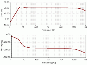
The gain vs. frequency response and phase vs. frequency can be seen in the picture below:


From the gain vs frequency curve seen the reinforcement that remains on rekuensi shift of 10 Hz s / d 100 KHz, meaning that the feedback function went well and the frequency response of the gain can be concluded that with the increase in frequency does not affect the resulting gain.

Saturday, February 1, 2014

Electronic Circuit Schematic Audio Oscillator using IC ICL8038

Eltronicschool. - In this moment Eltronicschool will try to share with you about one of simple electronic circuit schematic of Audio Oscillator using IC ICL8038. In here we will show global description about the working of IC ICL8038 to generate pulse and then we also give you the circuit schematic to built Audio Oscillator using IC ICL8038.

Circuit Schematic

Figure 1. Audio Oscillator Schematic using IC ICL8038 (Circuitstoday)

Component Lists
  1. R1,R2 ............... 4K7
  2. R4 ...................... 1K
  3. R5 ........................15K
  4. R6 ....................... 10K
  5. R7 ........................ 15M
  6. R8 ........................ 20K
  7. R9 ........................ 100K
  8. C1 ........................ 0.1 uF
  9. C2 ........................ 4.7nF
  10. D2 ....................... IN457
  11. IC1 ....................... ICl8083

Description

The electronic circuit schematic of Audio Oscillator using IC ICL8083 show like in figure 1 above. The main active component of this circuit is IC ICL8083. To know more about the description of this IC please follow the description below:
  1. The external timing capacitor (C2 in the circuit diagram) is charged and discharged using two internal current sources. The first current source is on all the time and second current is switched ON and OFF using a flip-flop. 
  2. Suppose the second current source is OFF and the first current source is ON, then the capacitor C2 will be charged with a continuous current (i) and the voltage across C2 increases linearly with time. 
  3. When the voltage reaches 2/3 supply voltage, controlling flip flop is triggered and the first current source is activated. This current source carries double the current (2i) making the capacitor C2 is discharged with a current i and the voltage across it drops linearly with time. 
  4. When this voltage reaches 1/3 supply voltage, the flip flop is resetted to the initial condition and the cycle is repeated again.
Source: Circuitstoday blog.