Showing posts with label Sensor Circuit. Show all posts

Tuesday, April 7, 2020

Circuit Schematic Aircraft Hangar Fire Alarm System using Flame Detector and Arduino Uno

Eltronicschool. - It is very important to protect aircraft hangar from fire with give the fire alarm system when the fire detected by flame detector installed. There are many flame detector used in fire alarm system likenear IR array detector, ultraviolet detector, infrared (IR) detector, UV/IR detector, Infrared thermal cameras etc.

In here we will give you one circuit schematic connection from aircraft hangar fire alarm system using flame detector and Arduino Uno. The flame detector in this circuit, we used infrared (IR) detector and Arduino Uno to manage data from flame detector.

Circuit Schematic

Figure 1. Circuit schematic of aircraft hangar fire alarm system using flame detector and arduino uno (Source: https://circuitdigest.com/)

Component Part
  1. Arduino Uno
  2. IR based flame sensor module
  3. Resistors
  4. LED
  5. Buzzer
Description

Circuit schematic like in Figure 1 above is Circuit Schematic Aircraft Hangar Fire Alarm System using Flame Detector and Arduino Uno. Flame sensor module used to detect the light and op-amp to control the sensitivity of flame detection. In aircraft hangar, this flame sensor is used to detect fire and provide HIGH signal upon the detection. Arduino Uno is used to reads the signal and provides alert by turning on buzzer and LED.

Flame Sensor 

A flame detector is one of the sensor that designed to detect and respond the presence of a flame or fire. In this aircraft hangar fire alarm system we used IR flame detector based on the YG1006 sensor which is a high speed and high sensitive NPN silicon phototransistor. This sensor module can detect infrared light with a wavelength ranging from 700nm to 1000nm and its detection angle is about 60°.  

Image Courtesy of Circuitdigest

This sensor module consists of a photodiode (IR receiver), resistor, capacitor, potentiometer, and LM393 comparator in an integrated circuit. We can adjust the sensitivity by varying the on board potentiometer. We need voltage between 3.3v and 5v DC for this sensor, with a digital output. Logic high on the output indicates presence of flame or fire. Logic low on output indicates absence of flame or fire.

Working of Flame Sensor with Arduino

Arduino Uno is a open source microcontroller board based on ATmega328p microcontroller. It has 14 digital pins (out of which 6 pins can be used as PWM outputs), 6 analog inputs, on board voltage regulators etc. 


Image Courtesy of Circuitdigest

Arduino Uno has 32KB of flash memory, 2KB of SRAM and 1KB of EEPROM. It operates at the clock frequency of 16MHz. Arduino Uno supports Serial, I2C, SPI communication for communicating with other devices. The table below shows the technical specification of Arduino Uno.

Article Source:

https://circuitdigest.com/microcontroller-projects/arduino-flame-sensor-interfacing

Wednesday, February 27, 2019

Project on How to Build Circuit Schematic Ultrasonic Proximity Detector Based on LM393 IC

Eltronicschool. - There are many aplication of using ultrasonic proximity detector as like when you want to build  an automatic flush toilet for your home or design a machine to taunt your cat every time you walks by.

In here we will show you one project on how to build by your self circuit schematic ultrasonic proximity detector based on LM393 IC look like shown in Figure 1 and Figure 2 below.

There two main part of this project called with transmitter and reciever. You need ultrasonic sensor as transmitter and also as reciever. The main IC used in this project is using LM393 IC. Beside we will give you all of the circuit schematic, we also will give you more description on how to build this project and continued to see more from original site. 

Circuit Schematic

Figure 1. The transmitter circuit of ultrasonic proximity detector (Source: www.jameco.com)

Figure 2. The reciever circuit of ultrasonic proximity detector (Source: www.jameco.com)

Component Part
  1. R1 3K 5% 1/4W Resistor
  2. R2 150K 5% 1/4W Resistor
  3. R3,R10,R14 330K 5% 1/4W Resistor
  4. R4 1.8K 5% 1/4W Resistor
  5. R5 470 5% 1/4W Resistor
  6. R6 10K 5% 1/4W Resistor
  7. R7 2.2K 5% 1/4W Resistor
  8. R8,R15,R17 1K 5% 1/4W Resistor
  9. R9 220 5% 1/4W Resistor
  10. R11,R19,R20,R22 100K 5% 1/4W Resistor
  11. R12 100K Potentiometer
  12. R13 10M 5% 1/4W Resistor
  13. R16,R21 1M 5% 1/4W Resistor
  14. R18 150 5% 1/4W Resistor
  15. C1,C3,C6,C15,C16 100nF Capacitor
  16. C2,C5,C8,C12 1µF Capacitor
  17. C4 33pF Capacitor
  18. C7 47nF Capacitor
  19. C9,C10 22pF Capacitor
  20. C11 22µF Tantalum Capacitor
  21. C13 100µF Capacitor
  22. C14 470µF Capacitor
  23. C17 10nF Capacitor
  24. D1,D2 1N914 Diode
  25. D3 Red LED
  26. Q1,Q2,Q3 2N3904 Transistor
  27. U1 Comparator Dual ±18 Volt 36 Volt
  28. U2 HEX Inverting Buffer/Converter
  29. U3 Standard Timer Single
  30. U4 Standard Regulator 9 Volt 2.2 Amp
  31. K1 12V SPDT Relay
  32. TB1 Terminal Block
  33. J1 2.5mm x 5.5mm Jack
  34. T1 12V 200mA Wall Transformer
Description

Circuit schematic like in Figure 1 and Figure 2 above are the transmitter and reciever of ultrasonic proximity detector based on LM393 IC. The main component in these circuit are ultrasonic sensors and detector and also IC LM393 IC.

Accordingly Jameco site describe that This circuit schematic has a maximum detection range of approximately 6 feet. When someone passes in front of the ultrasonic transceiver board, the contacts of relay K1 will close. The relay will remain energized while the device continues to detect a reflection. When there is no reflection, the relay contacts will open after 20 seconds. Photo 1 shows the assembled circuit on an experimenter's breadboard. And now you can follow step-by-step on how to build this project using link HERE.

Thursday, September 20, 2018

Project: How to Build a Voltage Sensor using LM741

Eltronicschool. - This is one of project to build voltage sensor using LM714. The main circuit schematic of voltage sensor using LM741 shown look like Figure 1. The main component in this project is LM741 IC.

In this time we will show you one project of voltage sensor circuit schematic based on LM741. Beside circuit schematic shown, we also will give you global description about this project.

Circuit Schematic

Figure 1. Circuit schematic of voltage sensor using LM741.
(Source: http://www.learningaboutelectronics.com)

Component Part
  1. LM741
  2. Resistor
  3. LED
Description

Circuit schematic like in Figure 1 above is voltage sensor using LM741. The main component used in this project is LM741. 

How it works

According learning about electronics site describe that reference voltage of 5V connected to the inverting terminal. This 5V forms our voltage threshold level. If the voltage at the noninverting terminal is less than 5V, then the output will be off or LOW. If the voltage at the noninverting terminal is greater than 5V, the output will be on or HIGH. To the noninverting terminal, we connect the test voltage signal we want to test.

How the circuit works is very basic. If the voltage at the noninverting terminal is less, the LED is off. If it is greater, the LED turns on. This is how we form a voltage sensor circuit based on any voltage value. We can, of course, change the voltage anywhere from -15V to +15V.

If you want to be able to constantly vary the voltage, you can place a potentiometer either at the inverting terminal or noninverting terminal or both and connect it to greater voltage to get a greater varying range. But this is how a basic voltage sensor can work. 

Tuesday, July 31, 2018

Circuit Schematic HC-SR04 Ultrasonic Range Sensor

Eltronicschool. - This is one of the ultrasonic range sensor for you in this time to show you one of the circuit schematic of HC-SR04 ultrasonic range sensor like shown in Figure 1 below.

In this project with circuit schematic of HC-SR04 ultrasonic range sensor, you will show an how you can build the power inverter using special low cost in this time. 

Circuit Schematic

Figure 1. Circuit Schematic of HC-SR04 Ultrasonic Range Sensor (Source: Electroschematics)

Component Part
  1. STC11F (single-chip microcontroller, based on 1T architecture 80C51 CPU)
  2. MAX232 (dual EIA-232 driver/receiver)
  3. TL074 (low-noise JFET-input operational amplifier)
  4. 40-KHz ultrasonic transmitter and receiver pair (40T/R-B/W)
Description

According Electroschematics site describe thatthe HC-SR04 ultrasonic range sensor is a pretty cool pre-wired module that you actually enjoy using when you start playing with electronics, microcontrollers, and robotics. As you might have noticed, the most popular version of the module (comprised of an ultrasonic transmitter, ultrasonic receiver, and control electronics) has four interface pins — Vcc (5 V), Gnd (0 V), Trigger (Pulse In), and Echo (Pulse Out). The operating current of the module is about 15 mA at 5-V DC input, and its operating frequency is 40 KHz. The measuring range of the module is in the 2- to 400-cm range with a measuring angle of 15°.

Wednesday, December 13, 2017

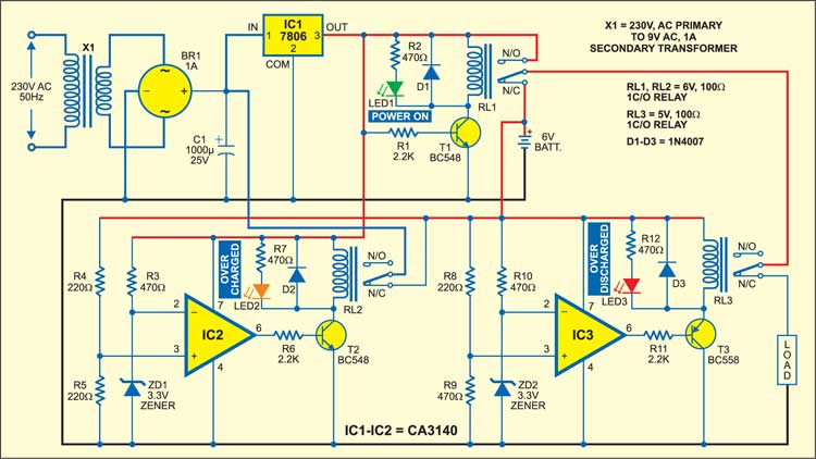
Circuit Schematic DC Changeover System with Battery Protection Unit using CA3140

Eltronicschool. - This is one circuit schematic for you who want to build DC changeover system in this time. Now, you can use the circuit schematic of DC Changeover System with Battery Protection Unit using CA3140 look like shown in Figure 1 below.

In this time, eside we will show you circuit schematic, we also will give you the description of this circuit and the last we will give you the link to read more about this circuit schematic from original source.

Circuit Schematic

Figure 1. Circuit Schematic DC Changeover System with Battery Protection Unit using CA3140 (Source: https://electronicsforu.com)

Component Part
  1. CA3140 IC
  2. Transistors
  3. Diodes
  4. LEDs
  5. Zener Diodes
  6. Resistors
  7. Relays
  8. Bridge Diode
  9. LM7806
  10. Transformer
  11. Capacitor
Description

Circuit schematic like in Figure 1 above is DC Changeover System with Battery Protection Unit using CA3140. Electronicsforu site describe that tthe AC mains is stepped down by transformer X1 (230V AC primary to 9V AC, 1A secondary), rectified by bridge rectifier BR1, filtered by capacitor C1 and regulated by IC 7806 (IC1) to get regulated 6V DC power supply.

The changeover circuit is built around IC1. When AC mains is available, npn transistor T1 (BC548) conducts to energise relay RL1 (6V, 100-ohm) and green LED1 glows to indicate the presence of AC mains. At the same time, the regulator’s output feeds the load through the normally-opened (N/O) contact of relay RL1 and the normally-closed (N/C) contact of relay RL3. When the battery is charging, power LED1 glows.

When AC mains fails, transistor T1 cuts off and relay RL1 de-energises. As a result, the load is now powered by the 6V battery through the N/C contact of relay RL1. Green LED1 stops glowing to indicate that AC mains is not present, and the load works off the battery.

And now you can read more about the DC Changeover System with Battery Protection Unit using CA3140 circuit schematic from original source using link HERE.

Thursday, February 16, 2017

Circuit Schematic Electromagnetic Field Sensor using 741 IC

Eltronicschool. - This is one of circuit schematic for electromagnetic field sensor using the main IC 741 that will help you to build of the many sensor reference in this time easily.

Beside we will give you circuit schematic of Electromagnetic Field Sensor using 741 IC, we also will show you the component list needed and also global description about this circuit from original source.

Circuit Schematic

Figure 1. Circuit Schematic Electromagnetic Field Sensor using 741 IC (Source: www.circuitstoday.com)

Component Part
  1. Inductor
  2. 741 IC
  3. Resistors
  4. Capacitors
  5. Variable Resistor
Description

Circuit schematic like in Figure 1 above is Electromagnetic Field Sensor using 741 IC. According Circuitstoday blog describe that this is a very simple circuit that can be used to sense electromagnetic radiations. The circuit can even detect hidden wrings. A 1mH inductor is used for sensing the electric field. The electric field will induce a small voltage in the sensor inductor and this induced voltage is amplified by the opamp.The headphone connect at the output of the opamp will give an audio indication of the electric field. For example, the electric field around a mains transformer can be heard as a 50 Hz hum. The POT R4 can be used to adjust the gain of the amplifier. By keeping the sensor inductor near to a telephone line, you can even hear the telephone conversations.

Tuesday, August 16, 2016

Circuit Schematic Heat Activated Cooling Fan Controller using LM35 Temperature Sensor

Eltronicschool. - One the temperature sensor is to detect heat and cool of the device that can open the heating. One of the popular temperature sensor that used in electronic project is LM35D that will give different voltage output according the temperature change. With using Op-Amp IC like LM385 as inverting system use, we will can build the circuit of heat activated cooling fan controller like in Figure 1 below.

Circuit Schematic

Component Part

  1. LM35D Temperature Sensor
  2. LM358 IC
  3. Resistors
  4. LED
  5. Diode
  6. Capacitors
  7. Variable Resistor
  8. C828 Transistor
  9. D400 Transistor
  10. DC Fan Motor
Description

Circuit schematic like in Figure 1 above is Circuit Schematic Heat Activated Cooling Fan Controller using LM35 Temperature Sensor. As published by Electronics-Lab site describe that heat activated cooling fan controller is a simple project which operates a brushless fan when the temperature in a particular area goes above a set point, when temperature return normal, fan automatically turns off. The project is built using LM358 Op-amp and LM35 temperature Sensor. Project requires 12V DC supply and can drive 12V Fan. This project is useful in application like Heat sink temperature controller, PC, heat sensitive equipment, Power supply, Audio Amplifiers, Battery chargers, Oven etc

The SMD SO8 LM35 used as temperature sensor, LM358 act as comparator and provides high output when temperature rise above set point, high output drive the Fan trough driver transistor. The LM35 series are precision integrated-circuit temperature devices with an output voltage linearly-proportional to the Centigrade temperature. The LM35 device has an advantage over linear temperature sensors calibrated in Kelvin, as the user is not required to subtract a large constant voltage from the output to obtain convenient Centigrade scaling. The LM35 device does not require any external calibration or trimming to provide typical accuracy of ±¼°C at room temperature. Temperature sensing range 2 to 150 centigrade. LM35 provides output of 10mV/Centigrade.

So, you can using electronic circuit schematic like in Figure 1 above to build by your self Heat Activated Cooling Fan Controller using LM35 Temperature Sensor.

Thursday, April 14, 2016

Circuit Schematic Zero Degree Celcius Alarm using Thermistor and LM7215 IC

Eltronicschool. - Thermistor is one electronic component that can detect air temperature that used in many application. One application that we will show to you is to detect temperature for zero degree Celcius like electronic circuit schematic in Figure 1 below. 

Circuit schematic

Component Parts
  1. Thermistor
  2. LM7215
  3. Resistors
  4. Capacitors
  5. Transistor
  6. All components see in Figure 1 above
Description

Circuit schematic like in Figure 1 above is Circuit Schematic Zero Degree Celcius Alarm using Thermistor and LM7215 IC. According Circuitstoday site describe that this simple circuit will produce an alarm whenever the temperature falls below zero degree. A thermistor is used here to sense temperature. The op-amp LM7215 is used to compare the reference voltage and voltage from the thermistor network. Reference voltage is given to the non inverting input (pin3) of the IC and voltage from thermistor network is given to the inverting input (pin4).When temperature becomes less than zero degree the voltage at the non inverting input becomes larger than the voltage at the inverting input and the output of the op-amp becomes high. This makes the transistor Q1 ON and drives the piezo buzzer to make the alarm. In the power supply section, IC 7805 is used to derive 5V from the 9V battery. Read more here.

Wednesday, September 23, 2015

Circuit Schematic DC Motor Speed Sensor using OS25B10 and LM393 IC

Eltronicschool. - There are many circuit schematic designed to control speed dc motor like in Figure 1 below. In here we will give you specific Circuit Schematic DC Motor Speed Sensor using OS25B10 and LM393 IC. (You also can read: Circuit Schematic 12V LDO Solar Charge Controller using MOSFET)

Circuit schematic

Figure 1. Circuit Schematic DC Motor Speed Sensor using OS25B10 and LM393 IC

Component Parts
  1. R1 = 180
  2. R2,R3,R4,R6 = 10K
  3. R5,R7 = 1K
  4. D1, D2 = LED
  5. C1,C2 = 100nF
  6. OC1 = OS25B10
  7. IC1 = LM393
Description

Circuit schematic like in Figure 1 above is Circuit Schematic DC Motor Speed Sensor using OS25B10 and LM393 IC. According Electroschematics site describe that as stated, the circuity can be used to send calibrated pulses to a microcontroller-based tacho meter or similar circuit/device. The wiring of the hardware turned out to be deceptively simple. At the heart of the circuit is the OS25B10 transmissive optical sensor with phototransistor output (OC1).

Next is the venerable LM393 dual comparator chip (IC1) configured as a simple Schmitt trigger (schmitt triggers are fundamental circuits with several uses; one is signal processing, they can pull digital data out of some extremely noisy environments). The green indicator (LED1) indicates the presence of voltage applied, and the red indicator (LED2) monitors output of the motor speed sensor module. Recommended working voltage of the module is 4.5 to 5.5 volt dc.

Note that a 180R resistor (R1) is used here to limit operating current of the light emitting diode inside OS25B10 optical sensor (OC1). It might become necessary to alter this value in your prototype. Similarly, try to tweak the value of the 10K resistor (R2) to get a decent voltage swing based on your real life application. The last 10K resistor (R7) is an optional pull-up resistor.

Monday, June 15, 2015

Motion Sensing Security Light using Passive Infrared Sensor (PIR) Module Circuit Schematic

Eltronicschool. - Maybe you ever know about the name of Motion Sensing Security Light that can activate with a motion sensor rather than by a conventional light switch. In here we will show you one circuit schematic for Motion Sensing Security Light using  Passive Infrared Sensor (PIR) Module like in figure 1 below.

You must know that motion-sensing lights are great for lighting areas that you only use briefly, since they only stay on as long as you need. It is can turning off automatically after a few minutes, they prevent wasted electricity and help conserve energy resources like in your home. Besides, this lights for your home are great deterrents from burglars, who are startled by the sudden illumination and may believe someone awakes inside the home.

Circuit Schematic

Figure 1. Circuit of Motion Sensing Security Light using PIR Module / Electroschematics

Component Parts
  1. PIR Module
  2. Resistors (see figure 1)
  3. Capacitors (see figure 1)
  4. Diode (See figure 1)
  5. FET (see figure 1)

Description

Circuit schematic like in figure 1 above is Motion Sensing Security Light using  Passive Infrared Sensor (PIR) Module. According the schematic like in figure 1 above that  the electronics is very simple and straight forward. In the prototype, only one white LED (3.6V/1W) is used as the light source. After construction, the whole circuit should be housed in a suitable enclosure. The finished unit can be used indoors or outdoors, and can mount to either walls or ceilings of the detection area. The tricky security light can be powered from any external 12-volt dc power source with atleast 500mA output current capacity. Since the input supply is 12-volt, it is possible to connect two – three white LEDs (in series configuration) in lieu of the existing light source. No more changes required here (except in the value of resistor R5), but you should remember to increase the output current of the external 12-volt dc power source upto the actual demand.

One component that very important as sensor is Passive Infrared Sensor (PIR) Module that the diagram is look like in figure 2 below.

Figure 2. Diagram of PIR Module / Electroschematics 

According diagram in figure 1 above that In standby mode, output from the PIR sensor module is 0V, the gate of T1 is at 0V level and T1 is off. Capacitor C1 is now charged via R2 and D1, whereupon T2 comes on so that the light source (LED1) is switched on. When PIR sensor module detects motion, T1 whose gate is linked to the PIR sensor module, cuts off T2, so that the light source turns off. However, C1 is discharged fairly slowly through R4, so that the light source is not turned off immediately (goes out slowly). This turn-off delay may be varied by altering the values of C1 and R4.

Note that, in a PIR sensor module, its output goes to high-level (near 3.3V) for a finite duration after the motion detection, and revert to low-level (0V) thereafter. This time period can be changed by adjusting the on-board potentiometer of the PIR sensor module (refer PIR sensor-related articles and tutorials published elsewhere in this website). Finally, resistor R5 limits the operating current of the light source (LED1). Prototype was tested with a 33-Ohm power resistor (33R / 3W) as R5.

Source: Electroschematics