Showing posts with label Controller Circuit. Show all posts

Monday, February 4, 2019

Circuit Schematic Soft Button Type Motor Direction Controller using Transistors

Eltronicschool. - Do you need circuit schematic to control your small dc motor now. We recommend you to use this circuit schematic that can control dc small motor as used in recorder tape.

This is Soft Button Type Motor Direction Controller using Transistors circuit schematic. The main component used in this circuit are transistors PNP and also NPN types. So, please follow all circuit and components used look like in Figure 1 below.

Circuit Schematic

Figure 1. Circuit schematic of Soft Button Type Motor Direction Controller using Transistors (Source: http://www.electronic-circuits-diagrams.com)

Component Part
  1. Resistors
  2. Transistors PNP
  3. Transistors NPN
  4. Diodes
  5. DC Motor
Description

Circuit schematic like in Figure 1 above is Soft Button Type Motor Direction Controller using Transistors. Based on Electronics Zone site describe that When both the points A & B are “HIGH” Q1 and Q2 are in saturation. Hence the bases of Q3 to Q6 are grounded. Hence Q3,Q5 are OFF and Q4,Q6 are ON . The voltages at both the motor terminals is the same and hence the motor is OFF. Similarly when both A and B are “LOW” the motor is OFF.

When A is HIGH and B is LOW, Q1 saturates ,Q2 is OFF. The bases of Q3 and Q4 are grounded and that of Q4 and Q5 are HIGH. Hence Q4 and Q5 conduct making the right terminal of the motor more positive than the left and the motor is ON. When A is LOW and B is HIGH ,the left terminal of the motor is more positive than the right and the motor rotates in the reverse direction. I could have used only the SL/SK100s ,but the ones I used had a very low hFE ~70 and they would enter the active region for 3V(2.9V was what I got from the computer for a HIGH),so I had to use the BC148s . You can ditch the BC148 if you have a SL/SK100 with a decent value of hFE ( like 150).The diodes protect the transistors from surge produced due to the sudden reversal of the motor.

Monday, September 18, 2017

Circuit Schematic 3 Phase AC Motor Controller Based on MC3PHAC from NXP Semiconductor

Eltronicschool. - This is one application of the MPC3PHAC IC from NXP semiconductor to build 3 phase AC motor controller circuit schematic look like shown in Figure 1.

Using this circuit schematic you will perform 6 PWM signals for 3 Phase AC Motor controller. It’s very easy to make professional VFD combining with Intelligent Power Module (IPM) or 3 Phase IGBT/MOSFET with Gate driver.

Circuit Schematic

Component Part
  1. MC3PHAC IC
  2. LM7805 IC
  3. Resistors
  4. X-Tal
  5. Transistors
  6. Capacitors
  7. Variable Resistor
  8. Push Button Switch
Description

Circuit schematic like in Figure 1 above is 3 Phase AC Motor Controller Based on MC3PHAC from NXP Semiconductor. Accordingly Electronics-hub site that published this circuit describe that the MC3PHAC is a high-performance monolithic intelligent motor controller designed specifically to meet the requirements for low-cost, variable-speed, 3-phase ac motor control systems. The device is adaptable and configurable, based on its environment. It contains all of the active functions required to implement the control portion of an open loop, 3-phase ac motor drive. One of the unique aspects of this board is that although it is adaptable and configurable based on its environment, it does not require any software development. This makes the MC3PHAC a perfect fit for customer applications requiring ac motor control but with limited or no software resources available.

Included in the MC3PHAC are protective features consisting of dc bus voltage monitoring and a system fault input that will immediately disable the PWM module upon detection of a system fault.

All outputs are TTL signals, Input supply 5-15V DC, DC Bus voltage should be between 1.75V-4.75V, Dip switch provided to set the motor frequency 60 or 50 Hz, jumpers also helps to set the polarity of the output PWM Active Low or Active High and this helps to use this board with any kind of IPM modules since output can be set active low or high. Potentiometer PR2 helps to adjust motor speed. Refer to datasheet of the IC to change base frequency, PWM Dead Time, other possible parameters.

Speed Control — the synchronous motor frequency can be specified in real time to be any value from 1 Hz to 128 Hz by adjusting the PR2 potentiometer. The scaling factor is 25.6 Hz per volt. The SPEED pin is processed by a 24-bit digital filter to enhance the speed stability in noisy environments.

Acceleration Control — Motor acceleration can be specified in real time to be in the range from 0.5 Hz/second, ranging to 128 Hz/second, by adjusting the PR1 potentiometer. The scaling factor is 25.6 Hz/second per volt.

Fault Protection: The MC3PHAC supports an elaborate range of fault protection and prevention features. If a fault does occur, the MC3PHAC immediately disables the PWMs and waits until the fault condition is cleared before starting a timer to re-enable the PWMs. Refer to the graph in Figure 10 for the resistance value versus retry time from data sheet of the IC. Figure 10 assumes a 6.8 kΩ pull up resistor. In standalone mode, this timeout interval is specified during the initialization phase by supplying a voltage to the MUX_IN pin while the RETRY_TxD pin is being driven low. In this way, the retry time can be specified from 1 to 60 seconds, with a scaling factor of 12 seconds per volt.

Thursday, October 20, 2016

Circuit Schematic Unprogrammable Stepper Motor Controller using NE555 and CD4017 IC

Eltronicschool. - Now, there are many motor stepper controller that designed and developed using programmable circuit like Microcontroller. It is true make everything become easy but need some information about programming.

In here we will give you one circuit schematic of stepper motor controller without using programming that in this article mentioned with Unprogrammable Stepper Motor Controller. The main component in this circuit are NE555 and CD4017 IC like in Figure 1 below.

Circuit Schematic

Component Part
  1. NE555 IC
  2. CD4017
  3. Resistors
  4. Capacitors
  5. Stepper Motor
  6. Diodes
  7. Power Supply
Description

Circuit schematic like in Figure 1 above is Unprogrammable Stepper Motor Controller using NE555 and CD4017 IC. According ElectronicsZone that published this circuit describe that the circuit shown above can be used to control a unipolar stepper motor which has FOUR coils (I’ve swiped it off an old fax machine). The above circuit can be for a motor current of up to about 500mA per winding with suitable heat sinks for the SL100. For higher currents power transistors like 2N3055 can be used as darlington pair along with SL100. The diodes are used to protect the transistor from transients.

Monday, August 1, 2016

Circuit Schematic 4 Channels RF Remote Controller using PT2262 Encoder and PT2272 Decoder

Eltronicschool. - This is one pair of radio frequency transmitter and receiver remote controller with 4 channel application circuit schematic. In this circuit schematic the main component used are PT2262 Encoder and PT2272 Decoder like in Figure 1. as transmitter and Figure 2. as receiver.

Circuit Schematic

Figure 1. Circuit of Decoder – Receiver  using PT2272 (Source: Electronic-lab)
Figure 2. Circuit of Encoder – Transmitter  using PT2262 (Source: Electronic-lab)

Component Part

  1. PT2262 Encoder
  2. PT2272 Decoder
  3. Push button
  4. Diodes
  5. RF AM TX Module
  6. RF ASK Receiver Module
  7. Etc

Description

These are Circuit Schematic 4 Channels RF Remote Controller using PT2262 Encoder and PT2272 Decoder for you. Using this circuit you can implement many electronic project application like Car Security System, Garage Door Controller, Remote Control Fan, Home Security, Automation System, Remote Toys, Robots, and Remote Control for Industrial.

According electronic-lab site describe that 4 Channel RF remote built using PT2262 and PT2272-M4 IC from Princeton technology. PT2262 used as Encoder (Transmitter) and PT2272-M4 Decoder (Receiver) ICs are heart of the project. The receiver provides 4 channel Momentary outputs. All outputs are TTL level can be interface with other circuits or relay board. Transmitter works with 5V to 12V DC. Receiver works with 5V DC.

When any of SW1-SW4 (S1-S4) tact switch is pressed the, power is applied to encoder IC and RF transmitter module, the encoder then starts scanning Jumper J1-J8 and transmitting the status of the 8 bits address and data serially. The decoder IC receives the data and compares two times with J1-J8 address jumpers and provides outputs high and also VT LED goes On, if the data is Valid and address of Transmitter and Receiver are same. It is important to have same jumper settings J1-J8 at transmitter and receiver to pair both. Multiple remote can be used to control devices at same location by changing the address codes. All address is Tri-State and offers 6561 combinations.

Now you can read more the article with the title Circuit Schematic 4 Channels RF Remote Controller using PT2262 Encoder and PT2272 Decoder using link here.

Monday, May 23, 2016

Circuit Schematic Low-Cost Dusk-Dawn Controller using MOSFET IRF640

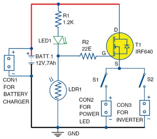
Eltronicschool. - There are many circuit schematic designed using MOSFET component for many application. One application is Circuit Schematic Low-Cost Dusk-Dawn Controller using MOSFET IRF640 like in Figure 1 below. (You also can read: Circuit Schematic 12V LDO Solar Charge Controller using MOSFET)

Circuit schematic

Component Parts
  1. LDR
  2. IRF640 MOSFET
  3. Resistors
  4. LED
  5. All components see in Figure 1 above
Description

Circuit schematic like in Figure 1 above is Circuit Schematic Low-Cost Dusk-Dawn Controller using MOSFET IRF640. According Electronicsforu site describe that Solar streetlights can be easily integrated with a dusk-dawn controller by simply employing a pnp transistor and a few resistors where the solar panel itself works as the sensor. But what about other lighting sources that do not employ solar panels such as automatic lighting systems in small wind turbines, automatic lighting in cars or battery based systems where automatic lighting is necessary?. 

The 12V battery-operated circuit is designed such that the common battery supply is used for operating the circuit as well as for load, that is, for power LED/small inverter circuit. Resistors R1 and R2 are used as a voltage divider and a current limiter in the circuit, respectively. LED1 is used as circuit de-activation indicator. LDR1 is the main component for actuation of the dusk-to-dawn sensing. The n-channel MOSFET IRF640 is for the switching action of the LED light or the small inverter connected to the system through switches S1 and S2, respectively.

Please read more about the Circuit Schematic Low-Cost Dusk-Dawn Controller using MOSFET IRF640 from original source using the link here.

Thursday, August 13, 2015

Circuit Schematic Fan Speed Controller using LM2941

Eltronicschool. - Here is simple circuit schematic of fan speed controller using LM2941 IC. (You also can read: Circuit Schematic Automatic Speed Controller for Fans and Coolers). As we know that there are many electronic circuits related to fan speed controlling have been published here and this one is just another approach.

In here we will show you one circuit schematic fan speed controller using LM2941 like in figure 1 below. Beside that, we also will give you global description about this circuit schematic of Circuit Schematic Fan Speed Controller using LM2941.

Circuit Schematic

Figure 1. Circuit Schematic Fan Speed Controller using LM2941 (Circuitstoday)

Component Part
  1. C1 = 470nF
  2. C2 = 470uF
  3. IC1 = LM2941
  4. R1 = 22K
  5. R2 = 10K
  6. R3 = 2.2K
  7. F1 = Fan
Description

Circuit schematic like in figure 1 above is Circuit Schematic Fan Speed Controller using LM2941. According Circuitstoday site describe that The circuit diagram shown here is of 12V DC fan speed controller using the IC LM2941CT which is a low drop out 1A voltage regulator. The IC has a dropout voltage as low as 0.5 and has also many useful features like power supply reverse protection, thermal protection, short circuit protection etc. The maximum output current the IC can source is 1A.

The 12V DC supply is connected between the Vin (pin4) and ground (pin3) of the IC. The load, which is the fan, is connected across the Vout (pin5) and ground (pin3) of the IC. The network comprising of potentiometers R1, R2 and resistor determines adjust current (Iadj) of the IC. By varying the Iadj using the POT R2 we can adjust the output voltage of the IC and hence the fan speed.

Saturday, August 1, 2015

Circuit Schematic Temperature Controlled Fan Regulator based on Triac BT136

Eltronicschool. - Do you want to make your self temperature controlled fan regulator based on Triac? circuit schematic like in figure 1 below show you Temperature Controlled Fan Regulator based on Triac BT136.

Circuit Schematic

Figure 1. Circuit Schematic Temperature Controlled Fan Regulator based on Triac BT136 (Circuitstoday)

Component Part
  1. Fan Motor
  2. C3 = 0.05 uF
  3. L1 = 700 uH
  4. R1 = NTC 100K
  5. R2 = PTC 5K
  6. C1 = 0.1 uF
  7. C2 = 0.1 uF
  8. T2 = DB2
  9. T1 = BT136

Description

Circuit schematic like in figure 1 above is Circuit Schematic Temperature Controlled Fan Regulator based on Triac BT136. According Circuitstoday site describe that this fan regulator circuit will automatically control the speed of your fan according to the temperature. Two thermistors (R1 and R2) are used to sense the temperature. The circuit works almost like the published here previously. Here the potentiometer is replaced by the thermistors. 

When the temperature is increasing the resistance of NTC thermistor ( R1) decreases and at the same time the resistance of PTC thermistor (R2) increases. At the same time, rate of change of the resistance will be different for R1 and R2.This action is similar to a potentiometer used in a conventional Triac based fan regulator. When the resistance is varied the firing angle of the triac changes and so do the speed of the fan.